- 您现在的位置:买卖IC网 > Sheet目录314 > ATMEGA1284P-XPLD (Atmel)MEGA-1284P XPLAINED EVAL KIT
�� �
�
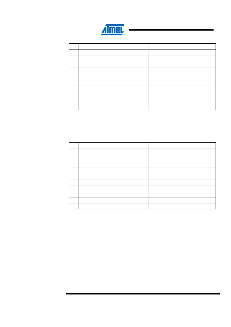
�Table� 4-4.� Atmel� MEGA-1284P� Xplained� I/O� expansion� header� –� J3.�
�Pin�
�1�
�2�
�3�
�4�
�5�
�J3�
�GPIO0�
�GPIO1�
�GPIO2�
�GPIO3�
�GPIO4�
�ATmega1284P� pin�
�PB0�
�PB1�
�PB2�
�PB3�
�PD4�
�Shared� with� onboard� functionality�
�SW0,� LED0�
�SW1,� LED2�
�SW2,� LED3�
�LED1�
�J4� (SPI� SS1),� DataFlash� (SPI� SS1)�
�6�
�7�
�8�
�9�
�GPIO5�
�GPIO6�
�GPIO7�
�GND�
�(1)�
�PD5�
�PC4�
�PC5�
�-�
�Filter� input�
�JTAG(TDO)�
�JTAG(TDI)�
�-�
�10�
�VCC_P5V0�
�(2)�
�-�
�-�
�Notes:�
�1.� This� signal� can� be� disconnected� from� the� filter� input� by� cutting� the� cut-strap�
�marked� FILTER� INPUT� in� the� SENSORS� &� FILTER� section� on� the� bottom� side�
�of� the� board.�
�2.� Pin� 10� of� header� J3� is� connected� to� the� USB� voltage� (VCC_P5V0).�
�Table� 4-5.� MEGA-1284P� Xplained� I/O� expansion� header� –� J4.�
�Pin�
�1�
�2�
�3�
�4�
�5�
�J4�
�TWI� SDA�
�TWI� SCL�
�USART� RXD1�
�USART� TXD1�
�SPI� SS1�
�ATmega1284P� pin�
�PC1�
�PC0�
�PD2�
�PD3�
�PD4�
�Shared� with� onboard� functionality�
�Header� J1,� board� controller�
�Header� J1,� board� controller�
�Board� controller�
�Board� controller�
�Header� J3� (GPIO4),� DataFlash�
�6�
�7�
�SPI� MOSI�
�SPI� MISO�
�(1)�
�(1)�
�PB5�
�PB6�
�Header� J1,� DataFlash,� board� controller�
�Header� J1,� DataFlash,� board� controller�
�8�
�9�
�10�
�SPI� SCK� (1)�
�GND�
�VCC_P3V3�
�PB7�
�-�
�-�
�Header� J1,� DataFlash,� board� controller�
�-�
�-�
�Note:�
�1.� These� signals� can� be� disconnected� from� the� board� controller� by� cutting� the� cut-�
�straps� marked� SPI� on� the� bottom� side� of� the� board.�
�8�
�AVR364�
�8377B-AVR-11/11�
�发布紧急采购,3分钟左右您将得到回复。
相关PDF资料
ATNGW100
KIT AVR32 NETWORK GATEWAY
ATSAM3S-EK
KIT EVAL FOR ATSAM3S4C
ATSAM3X-EK
EVAL KIT FOR SAM3X & SAM3A
ATSTK500
PROGRAMMER AVR STARTER KIT
ATSTK526
KIT STARTER FOR AT90USB82/162
ATSTK600
DEV KIT FOR AVR/AVR32
ATXMEGAB1-XPLD
KIT EVAL FOR ATXMEGAB1
AUIR2085S
IC DVR HALF-BRDG SELF OSC 8SOIC
相关代理商/技术参数
ATMEGA1284RFR2-ZF
制造商:Atmel Corporation 功能描述:2.4GHZ 128K SOC 48PIN IND 125C TRAY - Trays 制造商:Atmel Corporation 功能描述:IC MCU 8BIT 128KB FLASH 48VQFN 制造商:Atmel Corporation 功能描述:2.4GHZ 128K SOC 48pin Ind 125C Tray
ATMEGA1284RFR2-ZFR
制造商:Atmel Corporation 功能描述:2.4GHZ 128K SOC 48 PIN IND125C T&R - Tape and Reel 制造商:Atmel Corporation 功能描述:IC MCU 8BIT 128KB FLASH 48VQFN 制造商:Atmel Corporation 功能描述:2.4GHZ 128K SOC 48 pin Ind125C T&R
ATMEGA1284RFR2-ZU
制造商:Atmel Corporation 功能描述:2.4GHZ 802.15.4 128K SOC 48PIN TRAY - Trays 制造商:Atmel Corporation 功能描述:IC MCU 8BIT 128KB FLASH 48VQFN 制造商:Atmel Corporation 功能描述:2.4GHZ 802.15.4 128K SOC 48pin Tray
ATMEGA1284RFR2-ZUR
制造商:Atmel Corporation 功能描述:2.4GHZ 802.15.4 128K SOC 48PIN T&R - Tape and Reel 制造商:Atmel Corporation 功能描述:IC MCU 8BIT 128KB FLASH 48VQFN 制造商:Atmel Corporation 功能描述:2.4GHZ 802.15.4 128K SOC 48pin T&R
ATMEGA1284RZAP-AU
功能描述:开发板和工具包 - 无线 ATmega 1280V-8AU AT86RF230-ZU RoHS:否 制造商:Arduino 产品:Evaluation Boards 工具用于评估:AT32UC3L 核心:AVR32 频率: 接口类型:USB 工作电源电压:5 V
ATMEGA1284RZAP-MU
功能描述:开发板和工具包 - 无线 ATmega 1284P-MU AT86RF230-ZUU RoHS:否 制造商:Arduino 产品:Evaluation Boards 工具用于评估:AT32UC3L 核心:AVR32 频率: 接口类型:USB 工作电源电压:5 V
ATMEGA128-8AC
制造商:ATMEL 制造商全称:ATMEL Corporation 功能描述:8-bit Microcontroller with 128K Bytes In-System Programmable Flash
ATMEGA128-8AI
制造商:ATMEL 制造商全称:ATMEL Corporation 功能描述:8-bit Microcontroller with 128K Bytes In-System Programmable Flash